Manual Calculation Of True Position Chart
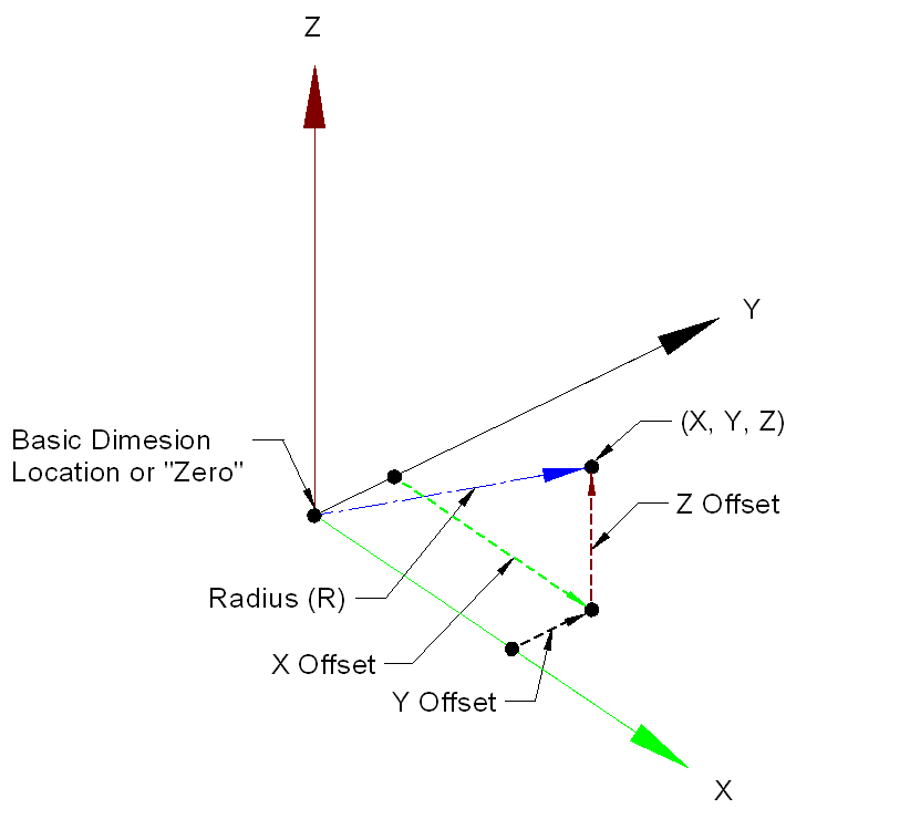
You need to know the basic dimensions of the drawing. This will calculate them for you. Put in the Tolerance according to the drawing. Check the Diameter checkbox if Diameter True Position. Fill in all the maximum and minimum dimensions from the drawing.
This will calculate the mean basic dimensions for you. Fill in the Actual X and Actual Y dimensions you measure on the part. If using Drawing Tolerance allows Maximum Material Condition, check the checkbox and fill in the Actual Hole Diameter on the part. No need to press Enter. Calculation is automatically updated whenever anything is changed.
When True Position calculated result is in RED, the value is out of tolerance. Maximum Material Condition - MMC If the tolerance callout has the M symbol then you are allowed extra tolerance. This extra tolerance comes from how much the actual size of the hole is larger than the minimum allowed size. Short-Cut Method For the short cut way, if you already know how much the hole is off in the X and Y direction, you can just put the deviation from basic in the Actual X and Actual Y boxes along with the Tolerance, and leave all the other boxes blank. MMC requires the min allowed diameter and the actual diameter of the hole. Inch or Millimeter input doesn't matter as long as you use the same everywhere. Radial or Diameter True Position.
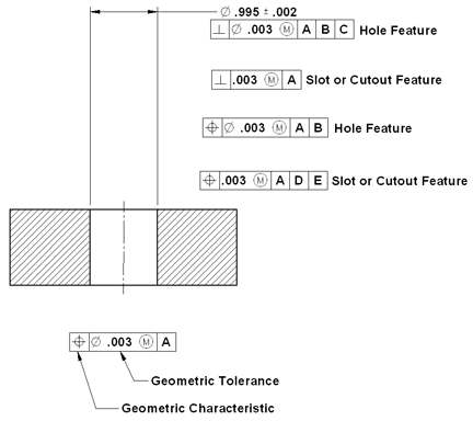
Most tolerances on the drawings you see will have the diameter symbol in the feature control frame. So.005 means the tolerance zone is a circle around the basic point with that diameter.
Without this symbol the.005 is a circle with that radius around the basic point - which is twice the size. Plus and Minus Dimensions You can also enter dimensions in the plus and minus form to make it easier if your drawing has this kind of dimensioning. Using only the Max edit boxes, after the main number add plus and minus symbol or just plus or just minus and then the second number, into the Max dimension box. You can also have 0.2525+.01.005 The min, max and mean are automatically calculated from this. You can see the calculated mean dimensions in parentheses. This can also be used for Basic dimensions. If you have basic dimensions on the blueprint you can put them in the Max box with a + or - on the end to signify a calculation.
Like, 0.2525+ Printing The Print button will print a picture of the form as shown on the screen. Menu The Main Menu is found by pressing the system icon on the window. Save/Load - On System Menu there are choices to save or load the current data to a file. Files have the.tpfile extension. Stay On Top - You can make the Program stay on top of all other windows by going to the system menu and choosing “Stay On Top”.
You need to know the basic dimensions of the drawing. This will calculate them for you. Put in the Tolerance according to the drawing.
Check the Diameter checkbox if Diameter True Position. Fill in all the maximum and minimum dimensions from the drawing. This will calculate the mean basic dimensions for you. Fill in the Actual X and Actual Y dimensions you measure on the part.

True Position Chart Inspectors Aid
If using Drawing Tolerance allows Maximum Material Condition, check the checkbox and fill in the Actual Hole Diameter on the part. No need to press Enter. Calculation is automatically updated whenever anything is changed. When True Position calculated result is in RED, the value is out of tolerance. Maximum Material Condition - MMC If the tolerance callout has the M symbol then you are allowed extra tolerance. This extra tolerance comes from how much the actual size of the hole is larger than the minimum allowed size. Short-Cut Method For the short cut way, if you already know how much the hole is off in the X and Y direction, you can just put the deviation from basic in the Actual X and Actual Y boxes along with the Tolerance, and leave all the other boxes blank.

MMC requires the min allowed diameter and the actual diameter of the hole. Inch or Millimeter input doesn't matter as long as you use the same everywhere. Radial or Diameter True Position. Most tolerances on the drawings you see will have the diameter symbol in the feature control frame. So.005 means the tolerance zone is a circle around the basic point with that diameter. Without this symbol the.005 is a circle with that radius around the basic point - which is twice the size. Plus and Minus Dimensions You can also enter dimensions in the plus and minus form to make it easier if your drawing has this kind of dimensioning.
Using only the Max edit boxes, after the main number add plus and minus symbol or just plus or just minus and then the second number, into the Max dimension box. You can also have 0.2525+.01.005 The min, max and mean are automatically calculated from this.
You can see the calculated mean dimensions in parentheses. This can also be used for Basic dimensions.
If you have basic dimensions on the blueprint you can put them in the Max box with a + or - on the end to signify a calculation. Like, 0.2525+ Printing The Print button will print a picture of the form as shown on the screen. Menu The Main Menu is found by pressing the system icon on the window. Save/Load - On System Menu there are choices to save or load the current data to a file.
Files have the.tpfile extension. Stay On Top - You can make the Program stay on top of all other windows by going to the system menu and choosing “Stay On Top”.

True Position GD&T Tolerance Calculator ( This calculator requires a)This calculator calculates position tolerances utilizing principles and concepts withinASME Y14.5-2009 and ASME Y14.5M - 1994, Geometric Dimensioning and Tolerancing (GD&T).For the equations behind this calculator, see:Negative Tolerance numbers indicateout of tolerance condition.This GD&T true position calculator willconvert coordinate measurements to position tolerances.